Click in the tree view to display the 802.15.4 SUN O-QPSK setup.
Choice: 470 MHz | 780 MHz | 866 MHz | 867 MHz | 868 MHz | 870 MHz | 915 MHz | 915-a MHz | 915-b MHz | 915-c MHz | 915-d MHz | 915-e MHz | 917 MHz | 919 MHz | 920 MHz | 920-a MHz | 920-b MHz | 2450 MHz
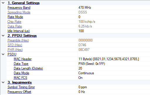
Default: 470 MHz
Coupling: Spreading Mode and Chip Rate
Select the frequency band for 802.15.4 SUN OQPSK PHY. See Table 21-2 in std 802.15.4-2020. It is not coupled with the Frequency under Instrument node, please set a proper center frequency for the signal after selecting the band.
Choice: DSSS | MDSSS
Default: DSSS
Coupling: DSSS is supported for all frequency bands, and MDSSS is supported only for780 MHz, 915 MHz, 915 MHz-a, 915 MHz-b, 915 MHz-c, 917 MHz, and 2450 MHz frequency bands
Select the spreading mode for 802.15.4 SUN OQPSK PHY.
Range: 0 | 1 | 2 | 3
Default: 0
Coupling: none
Select the rate mode for 802.15.4 SUN OQPSK PHY.
Choice: 100 kchip/s | 1000 kchip/s | 2000 kchip/s (depends on frequency band and spreading mode)
Default: 100 kchip/s
Coupling: Read-only on frequency bands except 780 MHz, 915 MHz, 915 MHz-a, 915 MHz-b, 915 MHz-c, 917 MHz frequency bands; its value depends on Frequency Band and Spreading Mode when it’s read-only
Select the chip rate for 802.15.4 SUN OQPSK PHY.
Range: none
Default: 6.25 kb/s
Coupling: Read-only and its value depends on Spreading Mode, Rate Mode and Chip Rate
Display the data rate for 802.15.4 SUN OQPSK PHY.
Range: 0 to 200000 us
Default: 100 us
Coupling: none
Set the idle interval in-between frames in micro seconds. When idle interval is set to zero, a continuous waveform will be generated.
Choice: 00000000000000 | 00000000
Default: 00000000 (Hex)
Coupling: The preamble sequence is "00000000000000" for780 MHz, 915 MHz, 915 MHz-a, 915 MHz-b, 915 MHz-c, 917 MHz, and 2450 MHz frequency bands and "00000000" for other frequency bands
Display the preamble for 802.15.4 SUN OQPSK PHY.
Choice: D746 (Hex)
Default: D746 (Hex)
Coupling: Read-only and it is fixed to be "D746 (Hex)"
Display the SFD field of PPDU in hex.
Range: none
Default: 00C497 (Hex)
Coupling: Read-only and it is automatically updated with PSDU settings
Display the PHR field of PPDU in hex.
Range: none
Default: 8821,01,1234,5678,4321,8765
Coupling: none
Click the button on the right to bring up an editor to configure the MAC Header.
Choice: PN9 | PN15 | Coutom Bit Pattern | User File
Default: PN9
Coupling: none
Set payload data type.
Range: 127
Default: 127
Coupling: none
Set the maximum data length of the payload field.
Range: 0 to 127
Default: 20
Coupling: none
Enter the length of payload in octets. Use space to split different length between different frame, the number of space separated values should be less than or equal to the number of frames.
Choice: Continous | Truncated
Default: Continous
Coupling: none
Select the data mode. Continuous mode will have data bits continuously distributed across multi-frame. Truncated mode will have the same payload data bits for all the frames, with the data size truncated for one frame.
Choice: On | Off
Default: On
Coupling: none
Enable or disable MAC FCS in the PSDU. When turned off, it can be used to simulate an invalid FCS case, since FCS part is actually filled with user data bits. See Figure 35 in IEEE Std 802.15.4-2011 for details.
Range: -300 to 300 ppm
Default: 0
Coupling: none
Set the symbol timing error of HRP UWB signal. The uint is ppm.
Range: -200 to 200 kHz
Default: 0
Coupling: none
Set the frequency offset of HRP UWB signal.